Hi everyone i have been working on this new design for over a day and i cant get my head around how to link the piston arm to the oil lever any one got any ideas please.
2 Likes
Wonderful watch! Unique and very interesting.
As for aligning the arms…
The arm on the right … I assume it is a separate image. Where is the centre of the image?
Have you placed it so the image centre is co-located with the lower pivot?
Not 100% sure what you mean co located ?
1 Like
oh sorry im tired miss under stood no its only 1 image did think about splitling in 2 but could not get my head around how to join them
1 Like
have a look at the inspection mode version see how you get on ok
1 Like
Ok. You will need to split the wheel and arm. The arm will need to rotate around its lower pivot.
Place the image of the arm into a larger blank PNG image such that the lower arm pivot is placed in the exact centre of the PNG image. In other words, treat the arm as if it were a watch hand. Then you can move the centre of the image in a circle around the wheel and rotate it so that the other end of the arm traces out an arc at a constant radius from the pivot of the top arm. The expression for the rotation of the top arm would then need to be adjusted to match.
I will have to think about the expressions …
It might take a while …

ok i did all most of that and the lower part now works fine its the top i can not get my head around i have tried lots of ideas but none seem to work also i dont care about the speed of the top oil rig bar i can make that match anything
1 Like
if it helps every item is on its own no sequences used. i wanted to make something from nothing so to speak lol i can create giffs or apng anims but they all look fake i wanted this one to look as real as possible
1 Like
I will try to see what I can come up with for expressions
Sorry I’m not getting very far …
I have ended up with two simultaneous equations in two sinusoidal variables but I am struggling to solve them.

Ok, I have found a solution. But it is complicated. Currently it is in a series of equations in EXCEL. It will take me a little time to transpose that into single expressions for rotation for the top and middle arms.
Can you tell me please:
A. Wheel
a. X Position
b. Y Position
B. Small arm that is part of wheel
a. distance ( to one decimal place ) from centre of wheel until centre of pivot point for next arm ( that is the point at which the next arm attaches to this arm )
C. Middle Arm
a. distance ( to one decimal place ) between the pivot points at either end of the arm
D. top arm
a. X Position
b. Y Position
c. Distance from centre point to end pivot point ( the point where the middle hand “attaches”)
…
I will take this data and come back with the expressions.
Hi please see attached to show the locations and sizes hope this helps
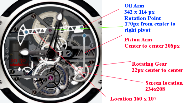
Thanks for that. Mmm, the centre locations look ok but the dimensions look off.
For example, position of oil arm is 160 pixel ( that is distance from left of image to centre = 160pixels ) but centre to rotation point is indicted as 170 pixels which should therefore be off the screen!
I guess you might be quoting the image dimensions before you place them in Facer; I really need the screen dimensions in Facer and/or the scale factors that apply.
In my case, all of my images get halved when I place them in Facer. Is it the same for you? Should I just halve these dimensions? Although, that does not seem right either; the piston arm centre to centre of 208 or 104 seems to be still too big ( ie. three times 104 = 312 so it should be possible to fit three lengths in a watch diameter of 320 pixels but just looking at it seems it would not fit ).
Ok I have had a look at your face iin inspection mode and approximately it looks like I should halve those dimensions, is that right?
Seems your right the dimensions are halved bt facer
1 Like
Ok, half works.
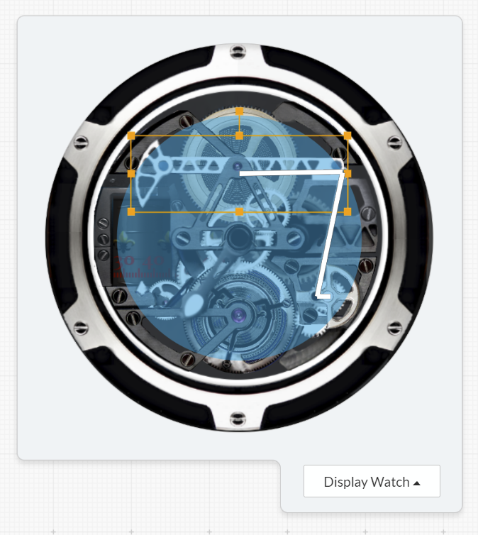
But you will need to modify the image of your oil arm so that the centre of rotation is in the centre of the image. And let me know the new centre location. As you can see in the image above, location 160x107 ( extreme left of my top arm ) is below and maybe a tad to the right of the centre of the oil arm.
I got it working using that approximation:
Oil arm
X: 160
Y: 103
WIDTH: 164
HEIGHT: 57
ROTATION: (-9cos(#DWFSS# 10/180*pi))
Piston Arm
X: (234+(sin(#DWFSS#* 10/180pi))13)
Y: (208-(cos(#DWFSS# 10/180pi))13)
WIDTH: 250
HEIGHT: 266
ROTATION: (-(sin(#DWFSS# 10/180*pi))*6)
It’s an approximation, so it’s not perfect but if you put the piston arm layer under the oil arm u will not see any bug.
Hope it helps
2 Likes
Ok, I have it working, I just need your new centre location ( after you adjust the image of the oil arm ) and I will update it with the correct expressions.
The link below includes the inspection mode …
…
I have tested it on my Samsung and it works ok. Not sure about other watches - the expressions include asin and acos functions and these are not listed in the list of expressions in the documentation so I am not sure if they are generally supported.
1 Like
I posted the updated expressions by email.
1 Like