So I was wondering how I would make a seconds hand that actually displayed the number around the face? I have uploaded just a quick example of what I mean.
Basically, the circle would move around the clock face and display each second within the white smaller circle.
2 Likes
There are a couple of tutorials on the Facer Community about that. One of them is here Time rotating with hand, possible? I think it will give you all the information you need.
4 Likes
I have a Draft set up with precisely that Seconds view that you’re after and Inspection is turned On 
7 Likes
Oh perfect! Thanks ICR!! Hi-5
3 Likes
IRC, Here it is. Thanks! Don’t pay much attention to the graphics as I am going to give it a big overhaul as it’s just too bright and I’m not liking that and some other elements.
7 Likes
That’s pretty cool, I like it, and those Viking Runes work really well. Just my opinion here, but I think the rotating Seconds would look better underneath the Hands 
2 Likes
Yes I agree!
I’m redoing this entire face after giving it some more thought. It just does not look good when I sync it. I actually prefer larger digital displays maybe because of my sight which is not bad but for some reason, I just can not see those small gauges or meters like on many analog designs.
2 Likes
It all works well aesthetically, just needs a little brightening up, and maybe a little transparency to the Black circle under the Seconds I’m not online right now, just using the App, but I’m keen to see your progress on this, so I’ll check back in again later…
2 Likes
Yeah but I don’t know something just does not sit right with me on this one. Like I said it is so bright that I think I may invert the colors with a darker BG and brighter clock hands.
3 Likes
It’s your Face my friend, I totally understand 
1 Like
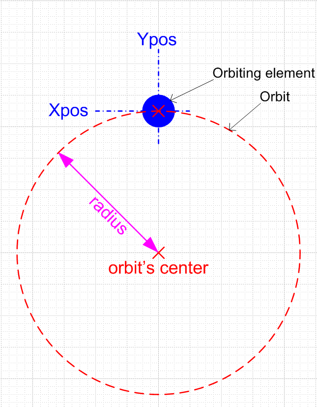
I struggled with this the first time I tried to orbit an element on a face (it was one of the Orakix challenges). After I finally got it, this is how I put it in my documentation:
X & Y positions for the orbiting element:
X=(((sin(rad((#DWFHS#))))*radius)+Xpos)
Y=(Ypos-((cos(rad(#DWFHS#)))*radius))
Where:
radius = radius of the orbit
Xpos = center of orbiting element’s X position
Ypos = center of orbiting element’s Y position
Text elements are not positioned by their center (which threw me off in the beginning) so you have to add an offset to Ypos, this seems to be about 1/2 the text element’s height.
EDIT: correction made to diagram
3 Likes
Just note, often these offset values have to be experimented, since each font aligns differently in the text field.
2 Likes
You are triggering my OCD here… you could at least keep them the same 
(and you have duplicate parentheses in the X one)
X=(Xpos+((sin(rad(#DWFHS#)))*radius))
Y=(Ypos-((cos(rad(#DWFHS#)))*radius))
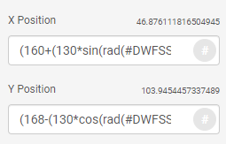
I always use:
X=(Xpos+(radius*sin(rad(#DWFHS#))))
Y=(Ypos-(radius*cos(rad(#DWFHS#))))
The reason for me to have pos and radius at the front, is so it is easy to see (and change) them right away in the small input field:
And if you have the text rotatating, your offset needs sin/cos functions as well 
See the number in the red part of this example I made a long time ago:
3 Likes
One might say (2*(2+1)) of one and half (4*(sqrt(9))) of the other  but yes, you’re right (OCD or not) – neatness counts and makes formulas easier to read. I pasted those right out of a working test face and didn’t pay attention to how they looked, and they got there after hours of struggling to figure them out.
What I actually intended to demonstrate in that post was the meaning behind the variables used in the orbiting formulas. A lot of times formulas are shown without going into detailed explanation of the elements used (hence the little graphic I made). Unfortunately, the same lack of detailed explanation goes for Facer’s tags and expressions (at least, for someone who likes details and is used to programming language syntax manuals).
Below was my final orbiting test once I finally figured it out. I didn’t want to just copy and paste an existing formula, I needed to understand the elements of the formulas, so that I can change them as I need to with different situations/dimensions/etc. Here I have 3 different moons orbiting the core: one that is (S) stationary, one that is (G) geosynchronous, and one that is (R) rotating in sync with the surface/circumference of the core.
2 Likes
I too love details, hence my reference to an “OCD” that I don’t really have (or do I?).
Yes, a picture > 1000 words.
I noticed an error though, the radius should go through the center of the orbiting element…
2 Likes
Well Done you guys . Another Fantastic Tutorial for Bookmarking .
Oh yes you’re right, the orbit circle is supposed to go through the center of the moon, as it does in the test face above. I corrected the original diagram.
2 Likes